
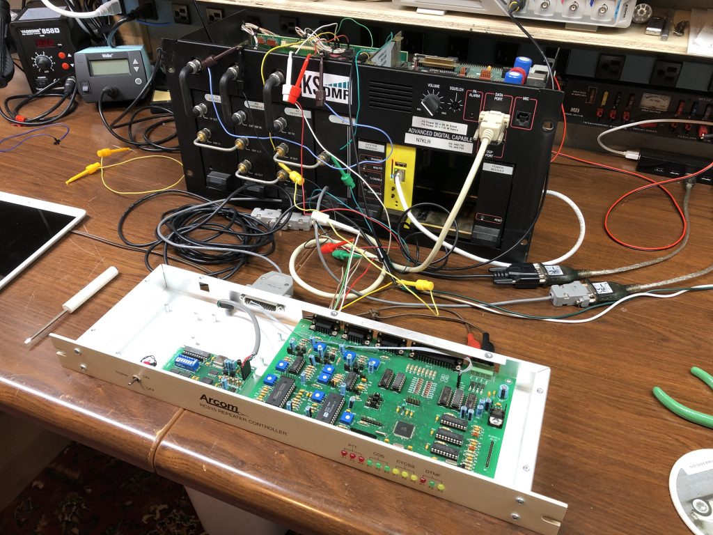
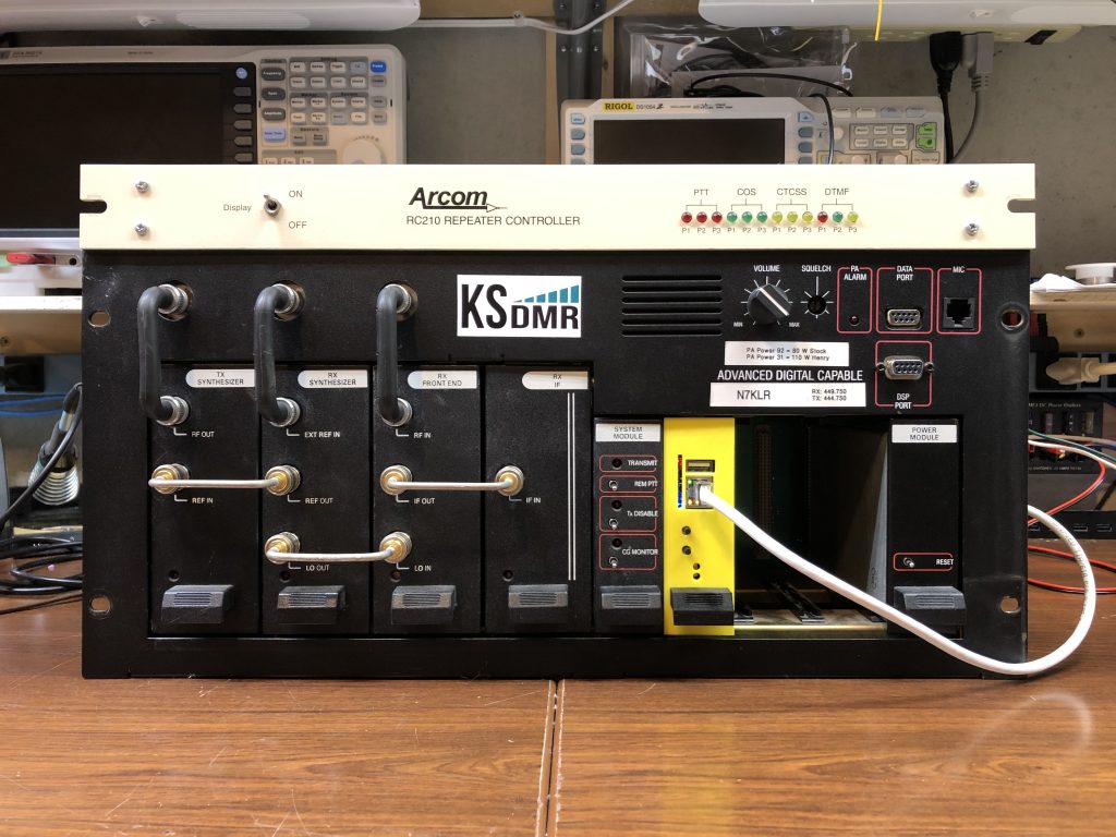
This is a common question I’ve been asked about both the STM32-DVM-MASTR3 and the STM32-DVM-MTR2K. When I went digital, I went pretty hard core. I haven’t had a ham repeater controller for a few years now. My brother Gavin, N0ECQ loaned me one and now I can work on articles about interfacing them with repeaters running my modems. The controller I used is mostly inconsequential. The signals used are typical of most ham controllers, and those with significantly more advanced configurations probably don’t need this article to begin with.
I started with the MASTR III because I’ve had more recent questions about it. I am happy to say, yes it does work and can be done. More importantly, I’m positive there are many more ways than one to do this, what’s included here is what I did for this article, which you may not want to do at all.
I started laying out the STM32-DVM-MASTR3 before even having a station to work with. Fortunately, Justin, NV8Q is a MASTR III master (pun intended), and was able to give me some great advice early on – the most important piece of which was to use the local PTT and external high speed data input for transmit audio. I might have been inclined to use the remote PTT, and I’m sure glad I followed Justin’s advice.
I interfaced the ham controller using the wireline “remote” interface on the MASTR III station as well as picking up the Local PTT (used by the modem to key the station, more on that later). Station connections include:
- Ground: P2.2 (DGND)
- RX Audio: P2.6 (LINE_A)
- TX Audio: P2.8 (DPLX_LINE_A)
- PTT: P2.14 (REMOTE_PTT_IN)
- RX Active: P3.5 (CAS)
- RX Unsquelched: P3.16 (RX_1_MUTE/SYS_RUS_OUT)
- Local PTT: P3.3 (LOCAL_PTT)
These should be pretty self explanatory. I used the CAS line (only indicates the receiver noise squelch is open) and the RUS (indicates squelch is open AND CTCSS/DCS requirements are met) to feed the “COR” and “CTCSS” inputs on my controller in this example, but it would be just fine in most cases to feed your controller’s “COR” (or equivalent name) input with the MASTR III RUS line.
My controller’s audio lines are AC coupled. I wasn’t able to find a real schematic of that section of the MASTR III, fortunately I didn’t have to worry about it with his controller. I intercept the wireline signals “Behind” the line transformers, which is why you don’t see differential connections – because these signals do connect to the line transformers, I suspect they are already AC coupled.
One word of warning about RX_1_MUTE/SYS_RUS_OUT and CAS – the logic signals on these lines are active high. If your controller doesn’t like this logic output directly, it may be necessary to add a transistor to make an open collector/open drain configuration.
The PTT line is active low, which should be pretty universal among controllers that likely have either an open drain/collector or relay contact output.
It really is just about that easy, but there are a few things to make sure are configured in the station. For this, I used MSEDIT.EXE, the MASTR III Station “Specials Editor”. I will only be covering the things I did to ensure the analog controller works – see the STM32-DVM-MASTR3 manual for configuring the station for the digital modem.
Only items that I call out in the text are relevant in the images included in this article. I do not intend readers to duplicate every setting they see in the images, they may not be correct for your station. I worked with an existing station and only changed things required to make the modem and controller work.
I’ll take this by the screens from MSEDIT. External CTCSS encode/decode is beyond the scope of this write-up, but it is necessary to use CTCSS (CG) or DCS (DCG) for the analog portion because otherwise, there’s no way for the station and controller to differentiate an analog and digital signal. In the channel screen (probably channel 1, like I have), make sure CG or DCG is set up per your requirements. Make sure that the following are set:
- N – Repeat Enable
- Y – RF Duplex Enable
- Y – REM PTT Enable
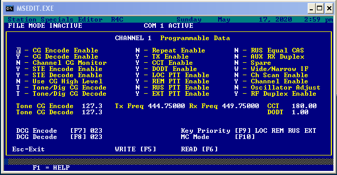
I also disabled the RUS PTT, as it’s not used, and kinda doesn’t make sense with in-cabinet repeat disabled, but of course it could be re-mapped to another purpose in the function lists. The next piece to configure is under “CONFIGURE SYSTEM”
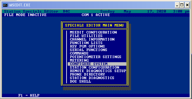
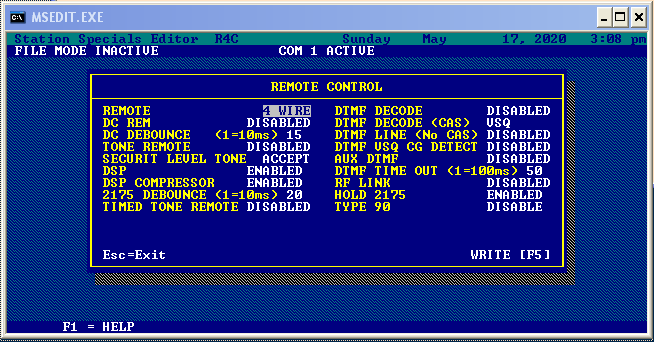
We have to ensure that the “REMOTE CONTROL”
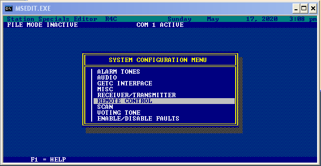
subsystem is configured for “4 WIRE” . We’re not actually using any DC REMOTE or TONE REMOTE commands, so “DC REM” and “TONE REMOTE” can remain disabled. I made no other changes to the remote control configuration.
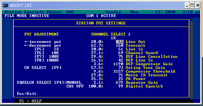
Chances are, this is enough to get things working, but there are a few more things to do. First off, the wireline audio lines both have soft pots that can be accessed under “POTENTIOMETER SETTINGS” from the main menu. “Line Out” is the RX audio to the controller, and “Line In” is the TX audio from the controller. Wireline interfaces are used to using high level signals – many volts peak to peak. I set them both at 20% as an initial value, and it seemed to work pretty well. Line out could probably be a bit lower, but neither the RX nor TX pots in the controller were all the way to the end of their range, so I called it good enough.
You might be tempted to be done at this point, because both controllers will work at the same time, but they still won’t work together. In order to ensure neither one tries to steal the transmitter from the other, there’s a little more to do. And the first half of this is the only thing we have to do with the STM32-DVM-MASTR3 modem.
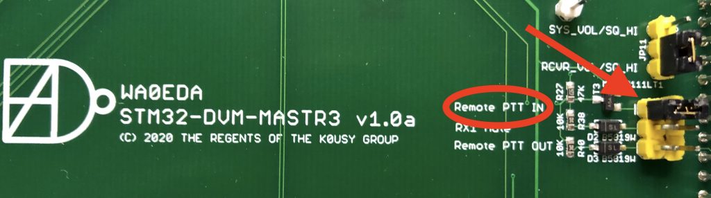
The STM32-DVM-MASTR3 may has three possible selections to “lockout” (disable) the modem. In this example, “Remote PTT IN” should be jumpered as show in the image above. We do this because Remote PTT is the signal the external controller will use to key the station. With this connected to the lockout, MMDVM will ignore incoming signals as long as our analog controller has the station keyed.
For more advanced configurations, it’s ok to jumper more than one lockout line if needed – and you’ll find that the “Function Lists” in the MASTR III configuration is one of the bright shining stars of this station! So that’s it for MMDVM not stomping on an analog QSO, what about the other way around?
This is where it will likely get controversial because of the number of ways this can be achieved… I had originally planned to rely on the MASTR III PTT priority to place the local PTT higher than the remote PTT. This would have allowed whichever mode was already transmitting to keep control until transmission ended (note the MMDVM get’s knocked down by a valid Remote PTT from the station already, protecting an analog transmission from interruption). This would have been great, except the two MASTR III stations I tried don’t seem to honor the PTT priority setting. Oddly enough, this does work when using the internal controller built into the station!
I really wanted a solution that did not involve anything extra in the external controller, which would make this write-up completely controller agnostic. Alas, it became necessary to connect the local PTT (found at connector P3.3, active low) and connect it to a logic input on the controller, which was then programmed to perform a “knockdown” function when the logic input is pulled low. Recall, local PTT is used by the MMDVM modem to key the transmitter, so following it allows the external controller to know when MMDVM is busy using the repeater.
Now we have a complete configuration where neither analog nor digital has priority over the other, but will both operate politely with the other. As long as the STM32-DVM-MASTR3 has the station keyed, the analog controller is effectively disconnected (RUS and Remote PTT are disabled) and when the station is keyed by the analog controller (Remote PTT), MMDVM is disabled.
5 comments on “STM32-DVM-MASTR3: MMDVM and an External Analog Controller”
Carsten
June 3, 2020 at 6:53 amHow are you powering the MASTR III on the bench?
Cort Buffington
June 3, 2020 at 8:07 am13.8VDC from my bench power supply to the power input on the T/R shelf.
Geep Howell
February 16, 2021 at 4:41 pmI have just acquired the M3 card and looking at setting up the radio. Nicely done, BTW! I see that you are not using the new (racing stripe) modules except the IF. Given that Harris requires the new ones for P25, curious as to how the older ones perform in this service. I have a UHF system with all new modules that I am planning to use but may want to get another card for VHF and don’t have newer cards in that range. Thanks, Geep WA4RTS
nv8q
February 21, 2021 at 5:46 pmGeep, the version of cards you have is not important for MMDVM. You will, however, need a backplane that is new enough that has the necessary signals going to the spare card slots. If your shelf says “Advanced Digital Capable” then it will work. If it’s older than that, some of the backplanes will work, and some won’t unless you do point to point wiring on the back side. You’ll need to consult the appropriate service manual for the exact version of the backplane you have to do this correctly.
Geep Howell
February 21, 2021 at 7:58 pmIt’s an ADC shelf. and I am familiar with the variations on earlier back planes, burnt up a couple of projects before I realized that all backplanes were not created equal! The ADC shelf will handle old or new modules, I just happen to have acquired a full set of the new ones in the right UHF range. I had it running with a P25 module, but even being in Lynchburg, there’s little interest in P25 with old commercial equipment. DMR and Fusion are the popular modes. Thanks for the reply.