
Editor’s Note: This board is currently available, and has been since shortly after this article was originally posted. For more information, navigate to the “Products from KS-DMR” section of this Web site.
After publishing the article MTR2000 and STM32-DVM-MTR2K: Analog + Digital, Playing Nice Together, the question almost immediately came up about availability and cost of MTR2000 Auxiliary I/O boards (CLN1206). Apparently, they’re not very easy to find, and can be prohibitively expensive. I said to myself, “How hard can it be to replicate the I/O functions of the Aux I/O board?”.
There isn’t a detailed service manual for the MTR2000, but the “Field Service Manual” sections on the Station Control Module (SCM, CLN1465) and Auxiliary I/O Board do provide an amazing amount of information on how these modules communicate. As it turns out, it’s a not entirely straightforward implementation (mode 3) of SPI (Serial Peripheral Interface). SPI isn’t the same as the typical serial port you find on a PC. I won’t go into details, but will note that it’s a synchronous serial bus with a single master device and one or more slaves. The master is almost always a microcontroller and slaves are typically hardware modules such as I/O expanders, sensors, memory devices, etc.
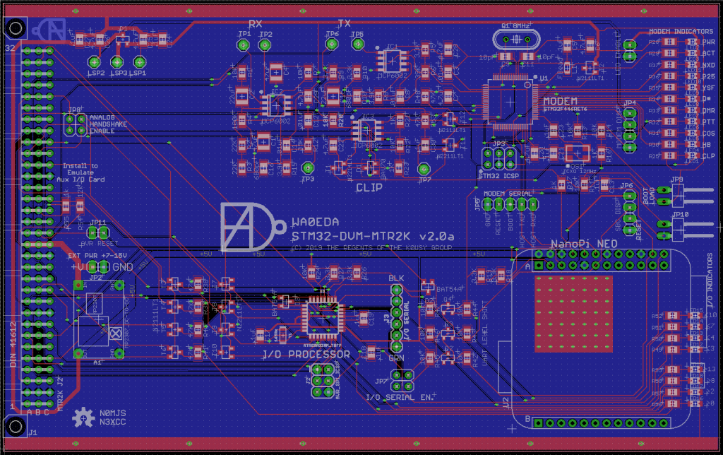
The driving force behind V2.0 of the STM32-DVM-MTR2K was to replicate the physical GPIO capability of the Aux I/O board, but there were a few other improvements too. The complete list is as follows:
- Add an additional display connector from the SBC
- Re-factor the analog circuit design (remove unnecessary components)
- Add functions of the original MTR2000 Aux. I/O card
- Create a virtual gateway between the SBC (NanoPi) and the SCM via the Aux I/O board GPIOs.
- Provide expansion bus access for the SBC on the J5 System Connector.
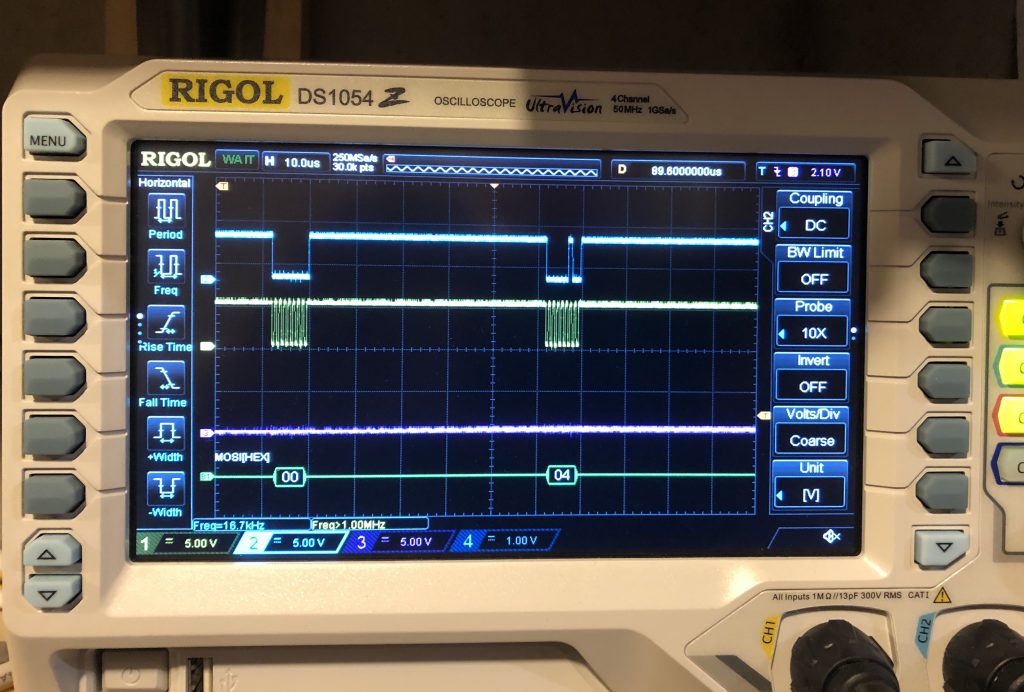
Thanks to the detailed theory of operation description in the MTR2000 Field Service Manual, figuring out how the SCM and I/O board communicate was easy. Unfortunately, what they were “saying” to each other was not included in the manual. As luck would have it – rarely the case with Motorola – the pattern turned out to be quite straightforward and reverse-engineered without much trouble. The MTR2000 SPI bus uses 16 bit datagrams, separated into two 8-bit bursts (in the same transaction). The GPIs (General Purpose Inputs) and GPOs (General Purpose Outputs) are treated as two separate SPI slaves on the bus. Each “slave” consisted of a pair of serially connected 8-bit shift registers on the Aux I/O board. The MTR2000 manual, RSS, etc. lists GPIs and GPOs by number. In fact, these are sequential and simply duplicated in the bit positions of the shift registers. That is to say, GPO_2 (they start numbering at 0), for example, is the 3rd least significant bit of the 16 bit datagram. This is depicted in the image below.
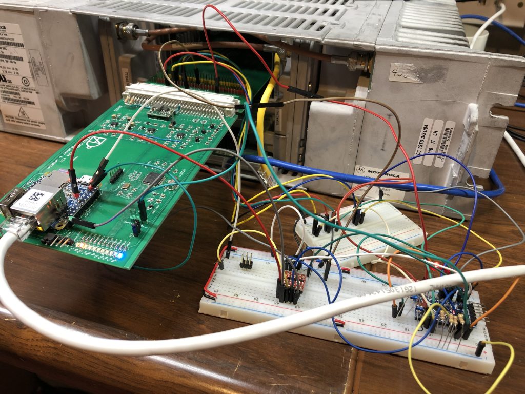
The Motorola MTR200 Aux I/O card is all logic hardware. No microprocessor. To put in four shift registers and re-gain the hardware I/O would have been easy. But in addition to the physical I/O, I wanted to build a “virtual bridge” between the MTR2000 SCM and the NanoPi NEO which would allow the Pi to both read and set the GPIO lines, virtually. The NanoPi NEO is not able to directly do this via the MTR2000 SPI Bus, and it lacks the GPIO pin count necessary to interface with discrete digital connections for each GPIO from the MTR2000. It became clear I would need to add a dedicated I/O processor.
The NanoPi NEO is running a general purpose operating system. While the NanoPi NEO’s CPU (AllWinner H3) has a hardware SPI interface, the use case for this interface is as a master. As a slave there are some very critical timing events that are better served in dedicated processing. Adding a separate, dedicated processor has an added benefit of ensuring any real physical GPIO functions continue to work if the NanoPi is offline (during a reboot, on power-up, etc.)
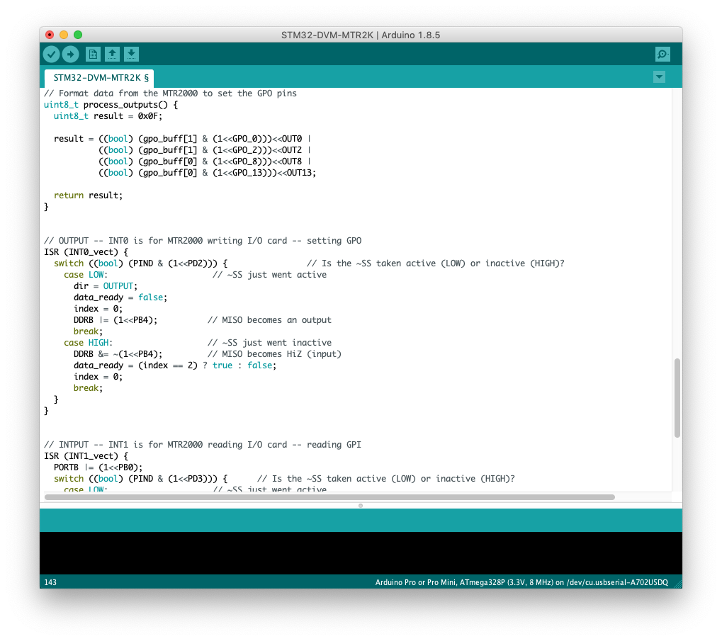
I chose the Atmel ATMEGA 328P for the job: It’s under $2, I know it well, has great C/C++ support, and I can use the Arduino IDE for programming (and so can you!) What’s not to like? The ATMEGA 328P is typical of devices in it’s class and only has a single 8-bit hardware SPI interface. The challenge became getting a single 8-bit SPI interface to act like the 2 separate 16-bit SPI interfaces that the MTR2000 was looking for. Since microcontrollers are generally not used as SPI slaves there’s little information about using them that way beyond the manufacturer’s data sheet. There was none at all about making them work with 16-bit data and reconfiguring on the fly to act as two separate slaves. I was on my own to find a solution.
I was triumphant! had I failed, you wouldn’t be reading this. As I type, the PCBs for V2.0a are in production at JLCPCB. I will be sharing all files for the PCB files, schematics, I/O processor software, etc. (look for my work on GitHub) I’m waiting to see the production PCBs work before I upload, but it should all be available within the next couple of weeks.
My goal with the V2.0 board was to both add new features, but also to create something of a blank canvas for others to expand on. Folks may wish to run their own custom code in the ATMEGA 328P to expand its capabilities or even the NanoPi’s. To that end, I’ve connected the I2C buses for both the Pi and the ATMEGA to the J5 System Connector on the back of the station (pads for I2C pull-up resistors are supplied). The NanoPI NEO and ATMEGA 328P communicate with each other over a standard asynchronous serial interface – I’m including the Arduino bootloader on the ATMEGA 328P as well, making it a snap to upload new code remotely. The only catch is that you can’t use the async port on the NanoPi for an MMDVM display AND have the NanoPi and ATMEGA 328P connected to each other. The ATMEGA can still be used, it just cannot communicate with the NanoPi in this situation. Not enough serial ports to go around – but the serial repeater through the MODEM is still available, and I can’t image too many folks wanting to run two displays on an MMDVM repeater.
Once again, I will be pointing folks to Scott Zimmerman over at Repeater Builder who want to buy this board with Scott’s full commercial production and support. I will be building and selling them directly as well, but I’m not set up to provide the full commercial support that Scott does.
Finally, I need to thank Keith Neufeld for the use of his Saleae logic analyzer. When I reached the point that my oscilloscope’s protocol analysis feature wasn’t enough, Keith’s logic analyzer made the job a whole lot easier.
12 comments on “Coming Soon: STM32-DVM-MTR2K V2.0”
John Place
September 25, 2019 at 3:28 pmOur county has two MTR2000 rptrs, 440 and VHF that I manage and would like to use the 440 version with your board. One question was asked, besides DMR will it do DS-Star also?
Where do we order a system from? Does it come complete just slide it in make changes and on the air?
Have my rptr on 443.800 at the present but have a d-star freq that could be used for DMR.
Cort Buffington
September 25, 2019 at 3:37 pmThe answers you’re look for can be found at: http://ks-dmr.net/products/
I’m going to assume you meant D-Star, and yes, it’s MMDVM. It does DMR, D-Star, YSF, NXDN and P25.
John Proctor
October 7, 2019 at 4:09 pmCort, I have one of Scott’s V3 boards for a raspberry Pi based system. The intent was to use it with the backup RF deck for our Club’s analogue repeater. This proved to be more difficult than expected so we have now gone down the route of obtaining an MTR2000 UHF repeater and your STM32 board is just what we will need. I have contacted Scott to see what his plans are for manufacture but I have not heard back yet so in the mean time I would like to follow up with you on your V2 board bedding in experience. Where are you with this? When will the detailed gerbers, BOM etc be put up on Github? We may need to build this ourselves as there doesn’t seem to be sources for complete boards.
Cort Buffington
October 7, 2019 at 4:54 pmV2 is now sold out! They went faster than I thought. Seems more folks were interested in V2 than V1 – which I did not expect. I’m not likely to post everything needed to DIY at this point, but haven’t decided for sure or not. Originally I intended to, but after a conversation with a potential builder I’ve put that on hold until I think it through a bit more.
Edwin De Looze Installatietechniek V.O.F.
October 13, 2019 at 12:46 pmGood evening, Cort Buffington, I’m interested in the printed circut board (STM32-DVM-MTR2K V2.0). Can I order this board? Where can I order it?
Cort Buffington
October 13, 2019 at 1:10 pmhttps://oshpark.com/shared_projects/Kbmjx9nd
Edwin de Looze
December 1, 2019 at 1:40 pmCort,
Can you tel me what type of ferrite bead I need. When I look at mouser.com then I find a servel of types, but I don’t know witch one I need.
Cort Buffington
December 1, 2019 at 2:57 pmIt’s not critical – use whatever you have kicking around that fits. I used a LI0805H151R-10, which is rated at 150Ω at 100MHz and a DC resistance of 10mΩ. That line draws no current to speak of… so no issues there.
Edwin
December 8, 2019 at 7:05 amCort,
thank nou i kan further when its ready i will sent a foto.
Edwin PA1EDL
Cort Buffington
December 8, 2019 at 6:51 pmI think you’re asking when it will be ready. It has been for months. Note the publication date on this article.
Rob Salsgiver
December 5, 2019 at 4:03 pmCort,
I see in some notes that the V2 board is sold out, yet the product page says the V1 is sold out, V2 indicates in stock with a new batch was on the way. Can you give an update on where things are?
Not sure if I’m reading things correctly, but not sure if the boards at https://oshpark.com/shared_projects/Kbmjx9nd are bare, assembled, or kits. (look like bare boards) If they are bare, are there kits or assembled boards available?
Would like to order 1-3 of the V2 boards, but this is the only way I can find on the website to send a question.
If I’m missing a contact link or path somewhere on the website, please let me know!
Cheers,
Rob – NR3O
Cort Buffington
December 5, 2019 at 4:20 pmThe link to OSH Park is for bare boards, not populated. I am supplying complete boards, there are no kit options. Contact me via e-mail: n0mjs@me.com