
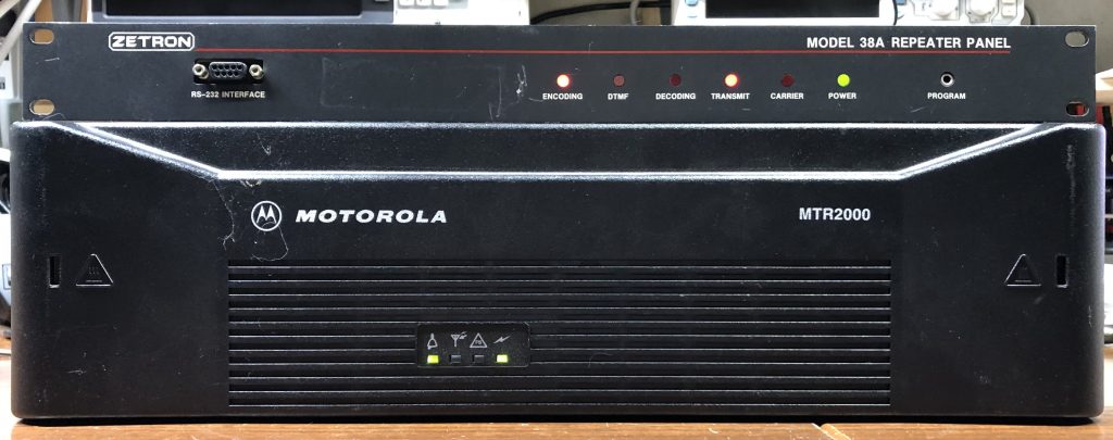
Here it is! The most asked for article and most often asked question since I introduced the STM32-DVM-MTR2K just over a year ago. Today we’re going to add an external analog repeater controller to an MTR2000 in parallel with an STM32-DVM-MTR2K. This is a long article because I cover multiple options for interfacing.
I’ll break the bad news to you right up front: I was unable to make this work without a wireline card installed in the station – even though I didn’t use the wireline card (I used the MRTI interface). This likely isn’t just a fluke. The wireline board contains PCM voice CODECs; I suspect one of them is used to enable full-duplex on the MRTI interface. The good news is that a wireline card capable of 4-wire/full duplex was included as standard in the MTR2000 station, though some of them on the secondary market may no longer have the card installed. Having the wireline card also opens the option of using the wireline interface for TX and RX audio as well.
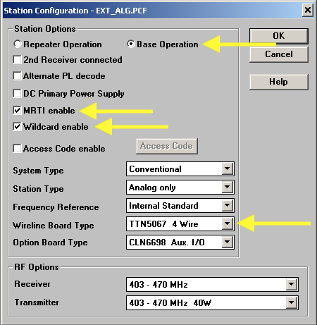
It is necessary to tell the station which card is installed, and whether it is to operate in 2 wire or 4 wire. There are a few other things set up as hown in the image below. The station should be set up for “Base Operation” in order to disable the internal controller. MRTI enable must be checked if you plan to use the MRTI connector. Finally, when selecting the wireline card installed, make sure to select “4 wire”. The option board type should already be selected and Wildcard enabled as part of using the STM32-DVM-MTR2K.
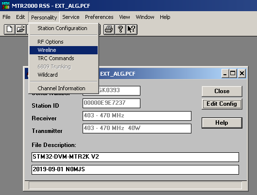
Selecting 4 wire does not put the wireline interface into full duplex. This must be configured specifically. The wireline configuration is found it the “Personality” Menu of the RSS .
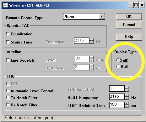
The wireline duplex type must be set to “Full”, otherwise the RX audio will be muted (wireline and MRTI) when the transmitter is keyed.
Unfortunately, there’s no useable COR/RUS signal available on the MRTI connector. There is one, but any time the station is keyed logically, it also activates this output. Because this will cause your controller to key the transmitter, this holds the COR/RUS signal and keeps the transmitter keyed until the repeater times out. Yep, others have discovered this too, and there appears to be no fix for it. Probably intentional since the MRTI interface was intended to be use with, well, a MRTI… or Motorola trunking controller, and not as a generic external controller interface.
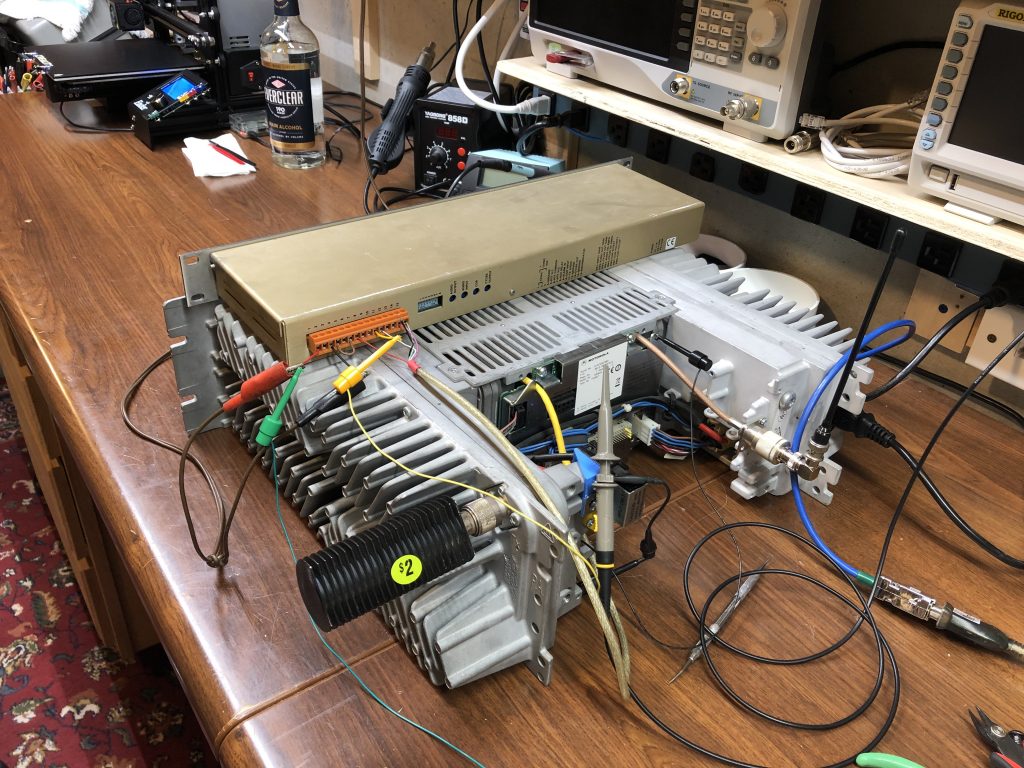
This article is all about options! The image below shows all of the connection points on the rear panel of the MTR2000. Not all of them will be used in any given install – don’t freak out, you’ll only use a few.
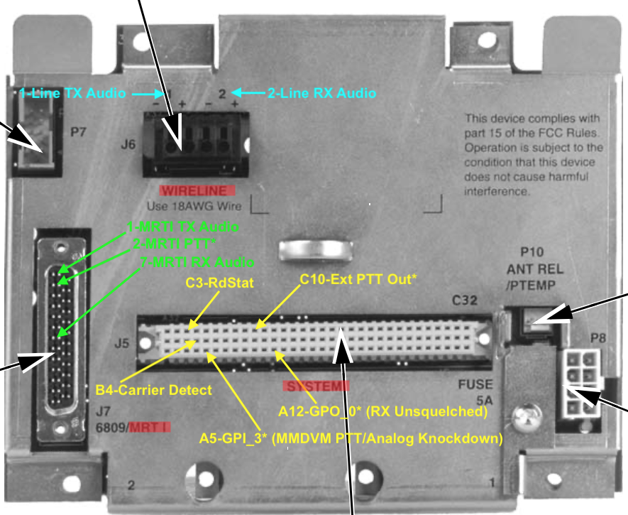
Here is a list of the connections from the image above. I’ve grouped the signals into logical categories, which I will discuss. (Note: * indicates active low). You can also follow these links to detailed lists for the MRTI and System connectors.
- TX Audio:
- MRTI TX Audio
- Line TX Audio
- RX Audio:
- MRTI RX Audio
- Line RX Audio
- PTT
- MRTI PTT*
- Unused GPO* programmed as “Key From Wireline”
- Receiver Unsquelched/COR:
- System RdStat (Receiver unsquelched)
- System Carrier Detect
- System GPO 0* (programmed as RX unsquelched)
- MMDVM Active (signal knockdown to analog controller)
- System GPI 3* (jumpered to Ext PTT Out via STM32-DVM-MTR2K)
- System Ext PTT Out* (used to signal that MMDVM is active)
- Ground
- Find a convenient pin, there are plenty!
The audio lines are pretty straight forward. Either the MRTI or wireline connections may be used. Because the extra equalization and differential signals are not needed, I chose to use the MRTI connections for my installation.
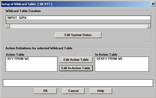
PTT is just as straight forward. If you use the MRTI audio lines, use the MRTI PTT. If you choose to use the wireline TX audio, a wildcard table will need to be assigned to an unused GPI (general purpose input) and programmed to “KEY FROM WL” (action) and “DEKEY FROM WL” (in-action). The wireline was to be keyed from a remote control tone, leaving no discrete electrical input for it. Since the STM32-DVM-MTR2K v2 includes many of the functions of the Aux I/O card (including GPIO and wildcard), creating the input is as simple as the RSS screenshot below.
COR or RUS – whatever you call the RX logic signals – present a few more options; all of which are available on the system connector (96 pin) on the rear of the station. For those looking for discrete connections for carrier and PL, “Carrier Detect” in position B4 and “RdStat” at C3 will do the job. RdStat is actually carrier and PL. Beware, both signals are active high, which is 5VDC.
Another solution, and the one I used, was to create my own carrier + PL logic signal with an open collector (active low) output on GPO 0. I did this with a wildcard table as shown below:
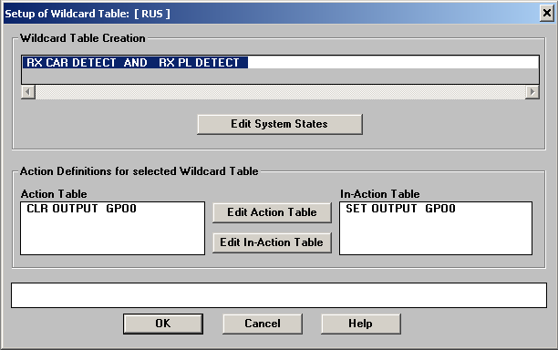
This logic feels backwards to me, but was exhibited with open collector outputs on the Motorola Aux I/O card, so I kept it that way in the STM32-DVM-MTR2K also – to “activate” an open collector output, you must “clear” it, to deactivate it, it must be “set”. Note, if a true PL only output is required (not supplied by RdStat), one can be created with a wildcard table and GPO.
The analog controller and MMDVM will now both work with the station, but they do not yet have the ability to handshake with each other to politely avoid transmitting while the other is already using it.
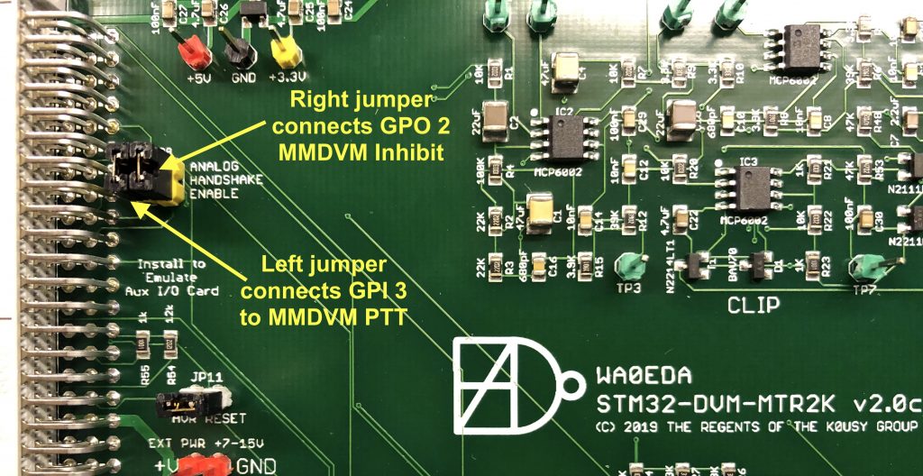
The STM32-DVM-MTR2K v2 was designed to include analog operaiton along side MMDVM using the built-in controller. Jumper block JP8 on the STM32-DVM-MTR2K connects the MMDVM PTT signal to MTR2000 GPI 3, and the MMDVM Inhibit input to MTR2000 GPO 2. This is covered in detail (including necessary wildcard tables) in the article MTR2000 and STM32-DVM-MTR2K: Analog + Digital, Playing Nice Together.
The goal is to make sure that MMDVM is inhibited when the analog controller is using the transmitter, and vice versa. For this article, I left both connected, but changed how they are used. To inhibit the MMDVM, I created a wildcard table entry to turn on GPO 2 when the MRTI TX is active, but I also added a dropout delay to keep MMDVM inhibited for 10 seconds longer than the analog carrier is up. This is the reason for using a wildcard table instead of simply jumping the MRTI PTT line to the GPO 2 signal on the System connector (making sure not to use GPO 2 for anything else!)
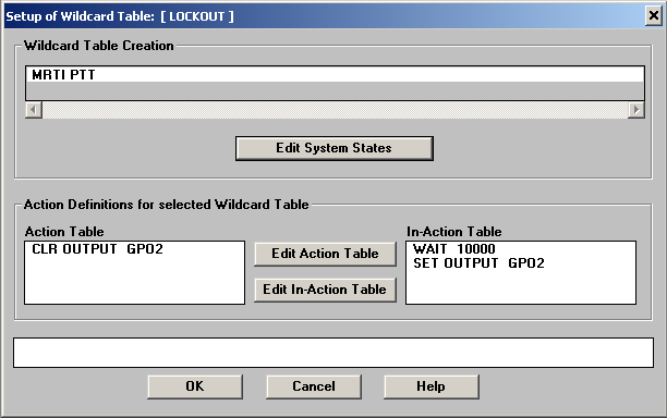
If the the wireline TX audio input is used the action/in-action [sic] items shown above could be added to the wildcard PTT table described earlier.
On the MMDVM side, the MTR2000 will always give priority to the Ext PTT source (and associated audio input – programmed as Aux TX Audio for the STM32-DVM-MTR2K), it is still probably desirable for the analog controller to “know” when MMDVM is active for more polite operation, logging, etc. The easiest way is to simply connect the “Ext PTT Out” (MMDVM’s PTT) found at C10 on the system connector to a logic input on your analog controller.
I chose to again use the jumper block JP8 on the STM32-DVM-MTR2K to connect the MMDVM PTT to MTR2000 GPI 3. In this case, I am not actually using the GPI 3 with a wildcard table, but merely using its pin on the system connector so that if I need to disable the “knockdown” logic signal to the external controller, I can simply remove the jumper. Wildcard could also be used to build a table that includes a dropout delay similar to what was used to inhibit the MMDVM, but as KS-DMR runs a very long DMR hang time (15 seconds), for my use, it was not necessary.
That’s it. I realized there are at least a couple more sane interfacing options while writing this article, but I’ve probably already covered more than enough to get you thinking. Thanks for reading; please enjoy a cute cat picture of the WA0EDA mascots.

2 comments on “STM32-DVM-MTR2K: MMDVM and an External Analog Controller”
Ken Jamrogowicz
March 9, 2021 at 8:31 pmHi Cort – Thanks for this article.
I have set this up with my NTR2K and STM32 board from Scott Z and it works – with one problem. When first powered up, the MTR2K goes into transmit right away and gets stuck there. If I then reboot the nano-pi, it clears the stuck-on condition and it is fine after that.
I wonder if there are some jumper on the wireline board that i have to do (or un-do)?
Any pointers would be appreciated.
Regards
Ken
nv8q
March 10, 2021 at 8:29 amKen,
Webmaster here. Cort only responds to support requests that come directly to him, FOR BOARDS HE BUILT. If you’re looking for support for a Zimmerman board I’d suggest going to him. Either way, I sure wouldn’t recommend trying to seek support in the form of a website article comment.
Thanks,
Justin