
(Editor’s note: This is the second installment of our series of posts on the Motorola MTR2000 repeater and MMDVM board. There will be future posts covering different aspects of the MTR2000/MMDVM integration. All articles in this series can be found by searching the “MTR2K” category.)
— Justin, NV8Q
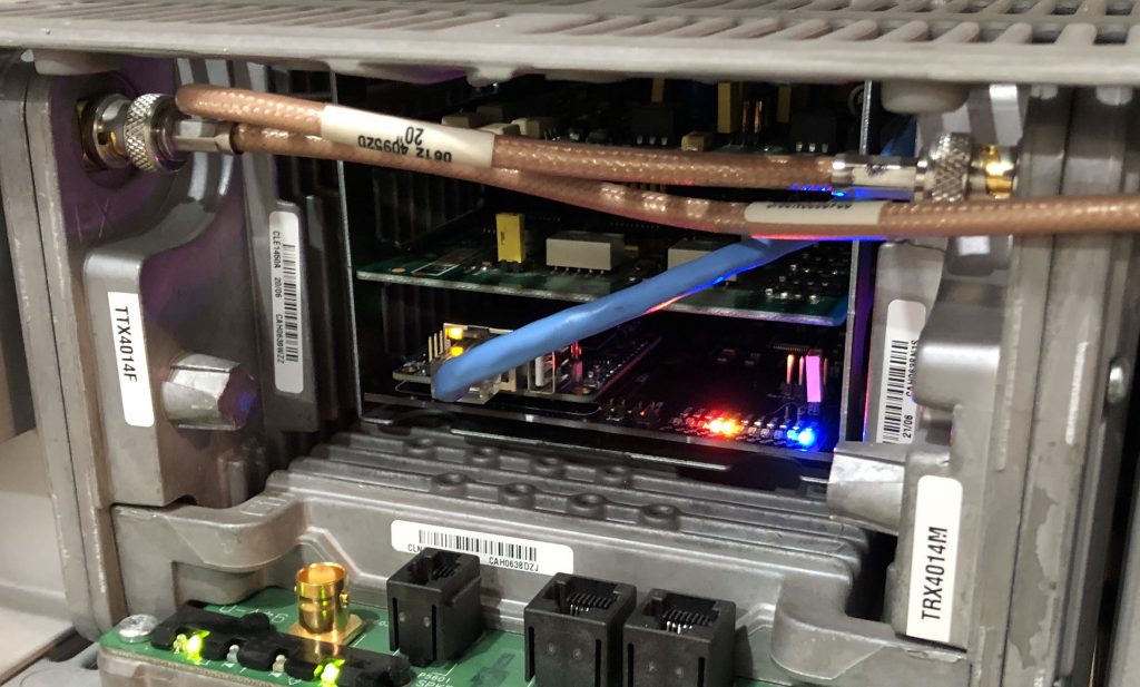
Previously I introduced the STM32-DVM-MTR2K, an integrated MMDVM modem and host on an easy-to-use plug-in-card for the MTR2000. In this post, I’ll discuss how to set up your MTR2000. First off, this isn’t a general write-up on using the MTR2000 with MMDVM. There are plenty of examples of that on the internet already. The best write-up I’ve seen (and probably the one most of the others are derived from) is by PD0ZRY and is located here. This article expects you to have some familiarity with Motorola RSS software and that you know how to configure it, which is beyond the scope of this article. If you need help, Google is your friend.
Likewise, this article will not cover setting up the OrangePi Zero/NanoPi NEO on the STM32-DVM-MTR2K. Most users will probably want to use Pi-Star, and I’ve never used it, so I’m not going to be much help there anyway. For those ready to dig right in, you need to know that the serial port is /dev/ttyS1.
Pi-Star users: The default serial port /dev/ttyAMA0 is correct.
This board is heavily based on the Repeater-Builder STM32-DVM. In fact, most of the documentation is identical, including the calibration procedure and firmware updates (though I recommend manually putting the board into boot loader mode.)
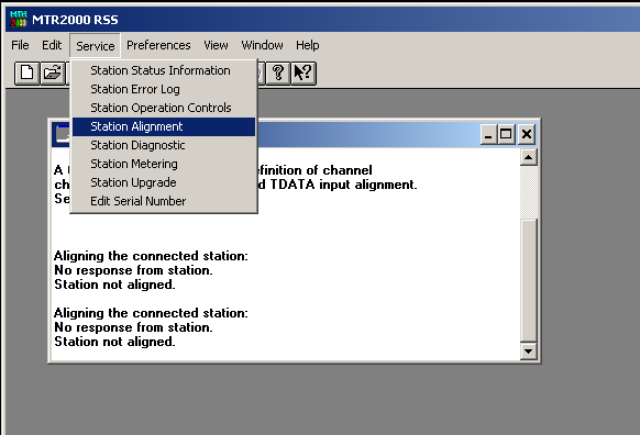
The STM32-DVM-MTR2K contains no trim pots. All configuration is done with the soft pots in the MTR2000. There are three things you’d normally calibrate: RX, TX and RSSI. The RSSI is fixed. You only need to run through creating a mapping file. You may note that on the top end, the MTR2000 will saturate the ADC for RSSI – but this also allows you to have useable resolution down in the -120dB to -125dB range – where it makes much more sense. To set the TX and RX levels, navigate to the “Service” menu in the RSS and select “Station Alignment”.
You’ll have to wait for a few seconds while the RSS reads the alignment information from your station. The sections we’ll be working with are the “Discriminator” button under “Audio Input/Output” and “Aux TX Input” under “Transmitter”. Calibration matches the procedure for the Repeater-Builder STM32-DVM.
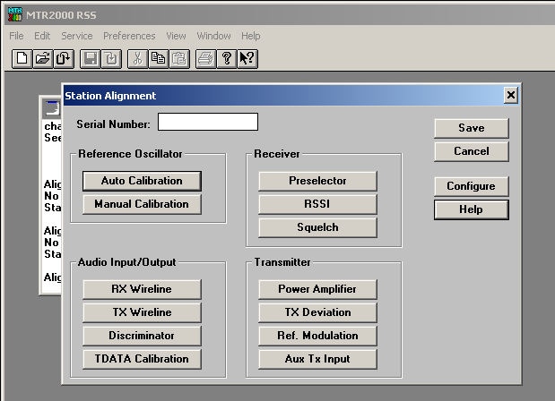
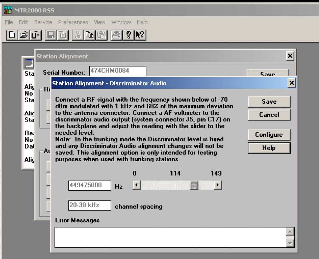
Since the STM32-DVM-MTR2K is optimized for the MTR2000, there is no need to have two RX audio adjustments. Follow the procedure for the generic Repeater-Builder board using the “clip” LED, only using the MTR2000 Discriminator output level adjustment instead of on-board pots. The sweet spot tends to be right around 110, so you might start there.
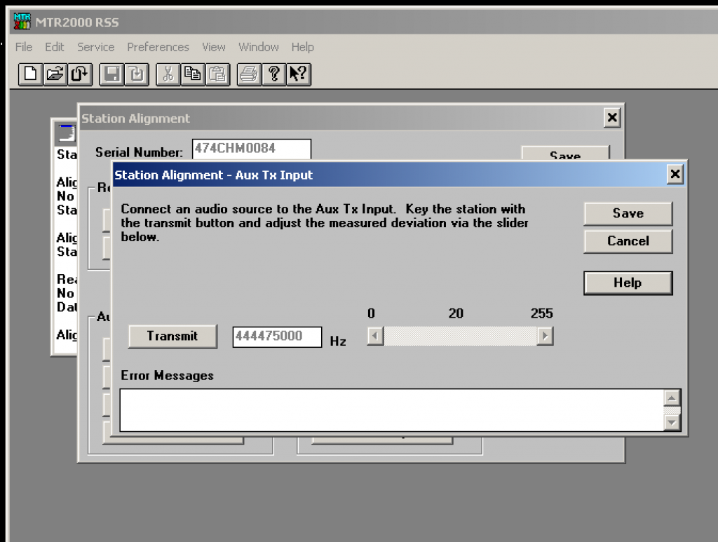
Transmit audio is pretty much the same and is done with the “Aux TX Input” adjustment. Use MMDVMCal and either set the deviation of the DMR test tone as described with the MMDVM documentation, or use a spectrum analyzer (25kHz sweep works pretty well) to set modulation as close to Bessel zero as possible. You will not achieve a perfect “null” using the Bessel zero technique as the soft pot’s steps are too coarse to do this. But if you note on a deviation meter how much change there is, between a perfect null and close to it, you’ll realize that the perfect null isn’t really necessary.
Pi-Star users: MMDVMCal is accessible at the bash prompt as root: pistar-mmdvmcal
Note: When adjusting Aux TX Input, the slider will not appear until you select the “Transmit” button. The slider appears when the station is keyed. The final result will be around 20 (EDIT: 26 if you’re using the latest WA0EDA builds), making that a good place to start.
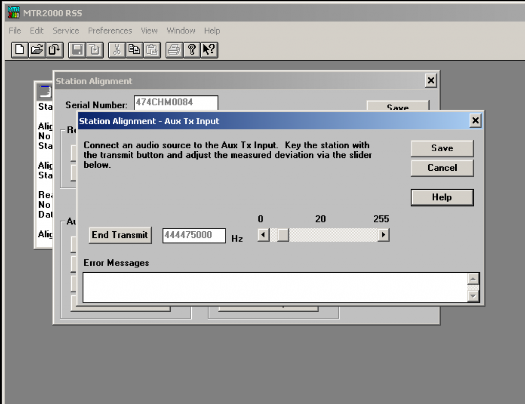
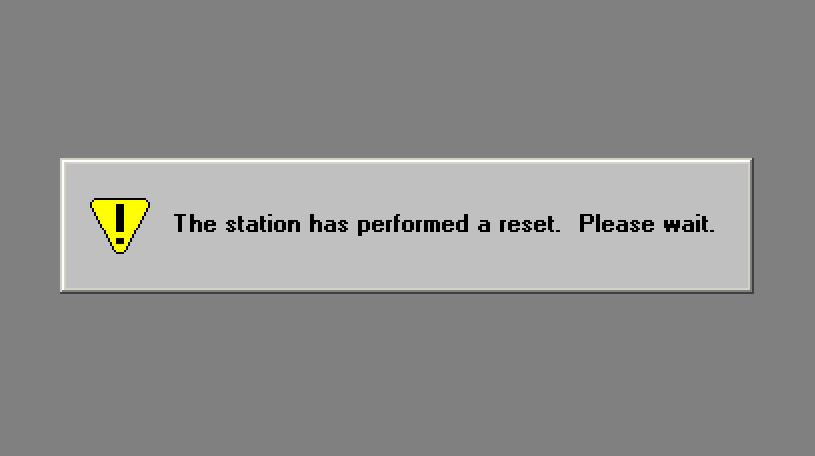
Make sure and use the “Save” buttons both on the individual alignment windows and then on the main station alignment window as well. Calibration values are not permanently written into the station until the main Station Alignment “Save” button is clicked. You know that you’ve actually written the station when you see it reboot.
This is all that is required for calibrating an MTR2000 with the STM32-DVM-MTR2K. There are a few more things that you’ll need to do in the radio’s channel settings. For this, you’ll need to first read your radio’s configuration (codeplug):
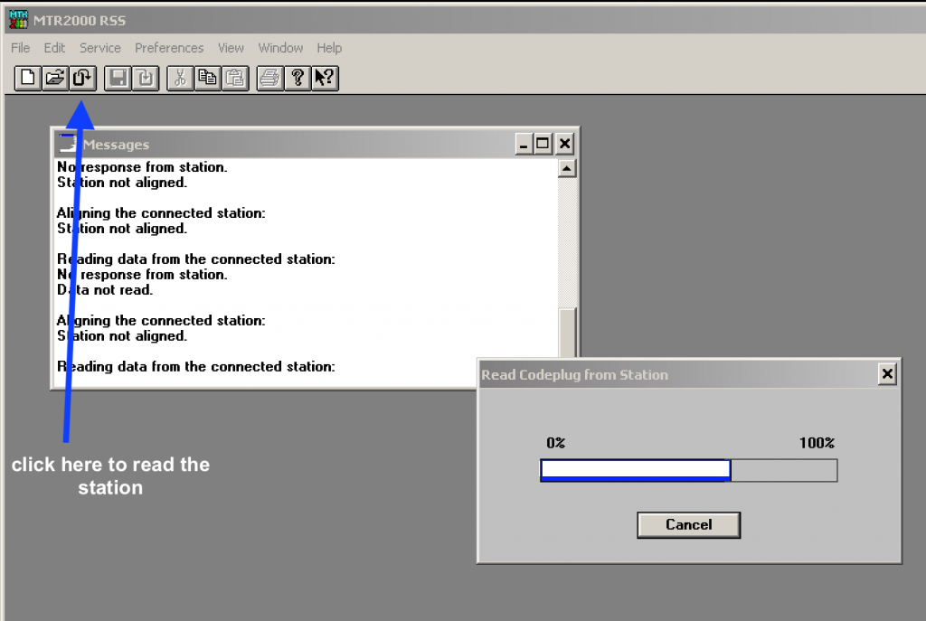
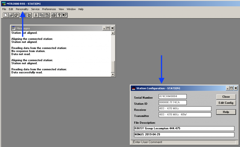
We need to ensure that, for the channel you will be using, two things are set: “Aux Tx Audio Control” and “External PTT Mapping”. Once the station is read, a new “Station Configuration” window will appear, and a new menu item called “Personality” will show up between “Edit” and “Service”. The personality menu is only present when a Station Configuration window is active.
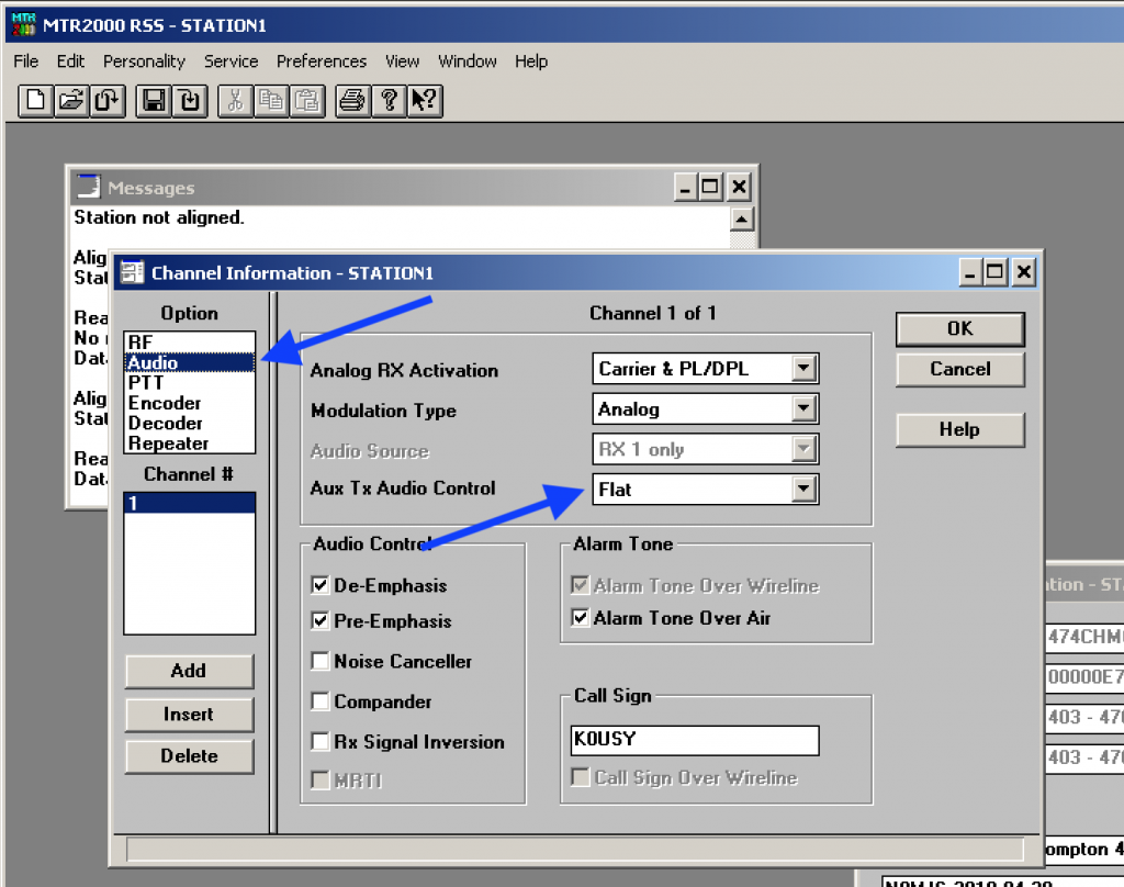
Under the “Personality” menu, select “Channel Information”. A new window will appear, in the upper left area of the window is a section box marked “Option”. From this list we’ll be working with the “Audio” and “PTT” options. In the Audio settings you will need to set “Aux Tx Audio Control” to the “Flat” selection from the drop-down list. This directs the station to NOT pre-emphasize or limit the Aux Tx Audio input.
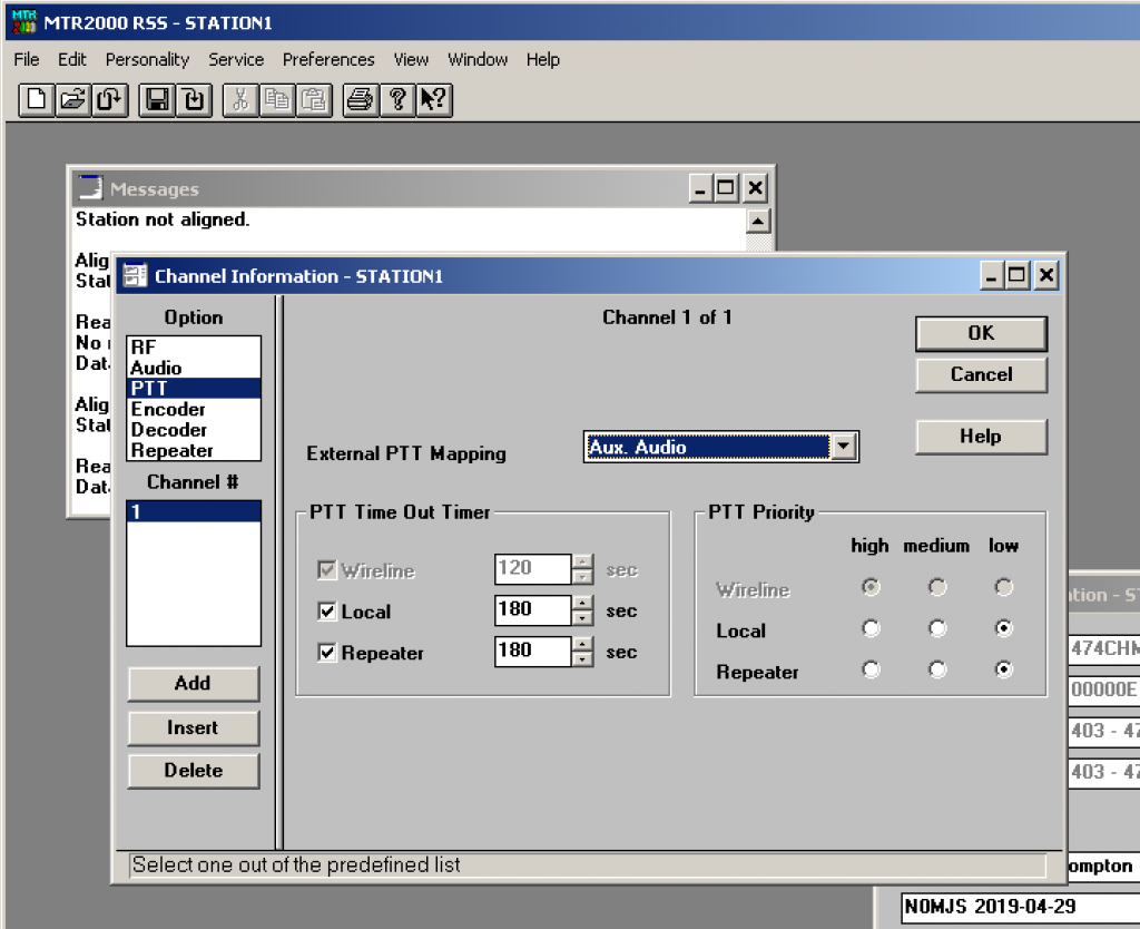
Finally, you will need to set the External PTT Mapping to “Aux. Audio” under the PTT section of the Channel Information window. This directs the station to use the Aux Audio input (that we previously calibrated) as the transmit audio input when the “External PTT” is triggered.
Make sure and click “ok” then write the station. None of the settings are stored until they are written back in, at which time the station will once again perform a reset. Now you are finished.
You will note that I did not get into any other general settings for the MTR2000. That’s because there are a number of possible configurations that work – and there are already write-ups aplenty about which configuration is better than someone else’s. Many are claiming that theirs is the only one that works. All I can say is – (as you might notice from what you see in my screen shots) that despite what you may read elsewhere, you can leave the station configured as a repeater and even engage the built-in analog control system. I do this to maintain the ability to troubleshoot the station, and as an emergency fall-back option. I also prefer using the CW ID built into the MTR2000 instead of MMDVM – but that’s my personal preference.
Note: In this configuration, MMDVM will NOT work politely with the built-in analog controller. Any MMDMV traffic will have priority over the station, Stay tuned for another write-up on how to make them both work together.
The STM32-DVM-MTR2K is a joint project between Repeater-Builder and WA0EDA. By sharing common design elements, we standardize firmware updates, troubleshooting procedures, and simplify the body of knowledge necessary to implement an MMDVM repeater. The WA0EDA Skunkworks thanks Scott Zimmerman, N3XCC for his willingness to collaborate on this project.
– Cort Buffington, N0MJS; Chief Engineer, WA0EDA
This article is part one of a three part series on the STM32-DVM-MTR2K. Click here to read part three or go back to part one.
12 comments on “Programming an MTR2000 for the STM32-DVM-MTR2K”
Mike Ess
June 10, 2019 at 3:32 pmCort,
With this set up, are RSSI values reported? On PiStar I am seeing -144 and S1 for ALL signals.
Cort Buffington
June 10, 2019 at 5:12 pmRSSI is functional on mine. You bought a board from Scott Zimmerman. It’s based on, but not my exact design. I cannot answer questions about it.
I do not and have never used PiStar, I cannot help you with it.
Mike Ess
June 10, 2019 at 6:05 pmThanks for the clarification that it isn’t exactly the same design. I wasn’t aware there were differences.
Mark DuMoulin
August 22, 2019 at 5:30 pmHello, an this board also act as an Allstar Node interface in the MTR-2000?
Tnx
nv8q
August 23, 2019 at 9:56 amNo.
Cort Buffington
August 23, 2019 at 10:35 amAs Justin said, it does not. The analog audio to/from the station go directly into a MODEM on this board, and would need to go into a generic ADC/DAC for AllStar Link. A version 3.0 board that adds this feature (and audio switching), or a standalone MTR2000 “sound card” based interface are things I’m considering, but since I have no personal use for it, would need a certain level of commitment from customers before making the investment.
mike bayard
January 20, 2020 at 1:24 amafter setting up a dozen of scotts st32mmdvm boards i have had nothing but fits with this new style no luck getting it to decode and list it as incompatible option board when you try to write with the board in place code { cln6698}
nv8q
January 20, 2020 at 4:43 pmIf you’re looking for support, you might want to do that via email directly with Cort.
mike
January 27, 2020 at 5:30 amyeah he helped me direct the sd files had issues
Mike Myers
December 30, 2020 at 8:07 pmIssues with TYT radios and Pi-Star on the STM32-DVM-MTR2K. I just loaded Pi-Star on to a new card and have been trying to get it to work on the STM32-DVM-MTR2K. I got it working with D-Star and DMR, or so I thought. The Anytone 868, 878 and the mobile (578?) all worked right off. I thought I had it. But none of the TYT radios work.
I only get the “Downlink Activate received from ….” and that is it. I read somewhere in the documentation that is normally the DMRDelay setting. I had it set to 165 and have gone as high as 168. I am just curious if anyone else has had problems with TYT radios and this symptom.
[…] curve. A group of hams, including WA0EDA, N0MJS, and N3XCC pulled out all the stops, creating the STM32-DVM-MTR2K. It slides into the card slots on the MTR2000, and all the tuning can be done through the MTR2000 […]
[…] Once that is done, click here to learn how to align the levels on the MTR2000 station. […]