
In the fourth installment on the STM32-DVM-MTR2K, I want to take a deeper dive into the system and go through two ways up update the firmware on the MODEM. One is manual, and the other is automated, which you can do remotely.
If you’re really impatient, skip to the end of this article to find a shell script for updating the MMDVM MODEM code on the STM32 microcontroller of your STM32-DVM-MTR2K. Just be warned: you need to have stm32flash and WiringPi installed to make it all work.
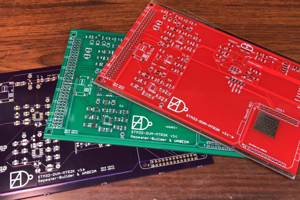
The similarities with Scott Zimmerman’s (N3XCC) general purpose MODEM are intentional. Not only are Scott and I working to standardize MODEM interface design, but also standardizing on the pre-built firmware from Steve Zingman (N4IRS) & Mike Zingman (N4IRR). Sure, this saves development time, but the bigger goal is to improve quality by not dividing attention between different electrical designs and firmware builds.
Background
MMDVM MODEM firmware is mature and seldom requires updating. But come on, we’re hams, we’re going to want to update it – even if there isn’t a real need! All of the boards have a way to put them into bootloader mode, which requires holding the bootloader enable pin on the STM32 high while resetting the processor (pulling it low). Here is where Scott’s boards and mine differ. Scott used a pair of pushbuttons, and I left jumpers (like the general purpose STM32-DVM). The logic is the same, but I only have my boards, so that’s what you’ll see here.
The jumpers are at right angles and can easily be accessed with the card installed in the MTR2000 station. For this write-up, I’ve taken photos with the cards removed because photographing inside the station is… well… not really possible.
The procedure is almost identical to that listed on the Repeater-Builder FAQ for the Scott’s original STM32-DMV version 3 PiHat (blue board) located here. You’ll need to reference that document, so now is a good time to click the link and open it up. I do not use (never have even loaded) Pi-Star, so I’m going to have to take some of it on faith. Everything I’m presenting was done on a system running MMDVMHost on Armbian Linux, without Pi-Star.
First off, you won’t have to download stm32flash from DVSwitch, because it’s now available directly. You only need to type:
sudo apt-get install stm32flash
If installed this way, the “./” in front of the “stm32flash” is not needed. I’ve also dispensed with the command line options to try and put the STM32 microcontroller into bootloader mode; I’ve never been able to get that to work correctly anyway, and those instructions were written expecting a RaspberryPi. With the OrangePi Zero or NanoPi NEO (both cases) and Armbian, it’s serial port 1 at /dev/ttyS1. When pulled together the exact command to flash the STM32 is:
stm32flash -v -w mmdvm_f4.hex -R /dev/ttyS1
Manual Method (using the jumpers)
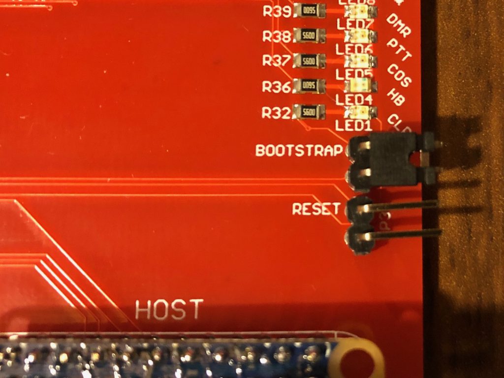
First, the STM32 microcontroller has to be placed into boot loader mode, and here’s where the jumpers come into play. The procedure is as follows:
- Ensure MMDVMHost is not running.
- Install the jumper on the bootloader header
- Momentarily short the pins on the reset header (pocket screwdriver for the win!)
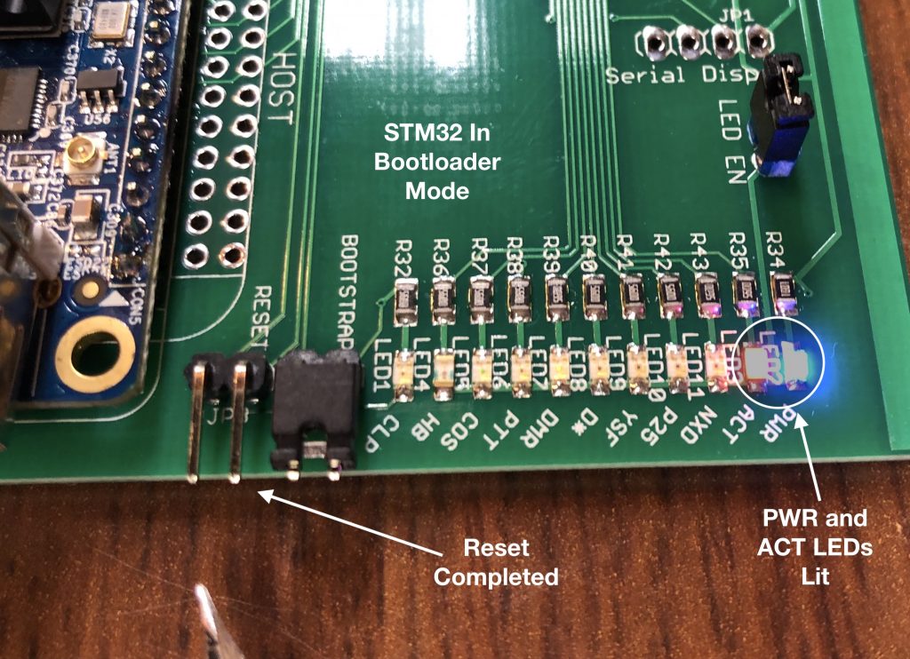
- The board should now be in bootloader mode (PWR and ACT LEDs lit constantly, all others off)
- Use stm32flash to write to the flash memory in the microcontroller. The ACT LED will blink while the flash memory is being written.
- While waiting for the write operation to complete, remove the jumper from the bootloader header
Let’s go through the jumper part in a little more detail. While the reset jumper pins are shorted, only the blue PWR (power) LED will be lit.
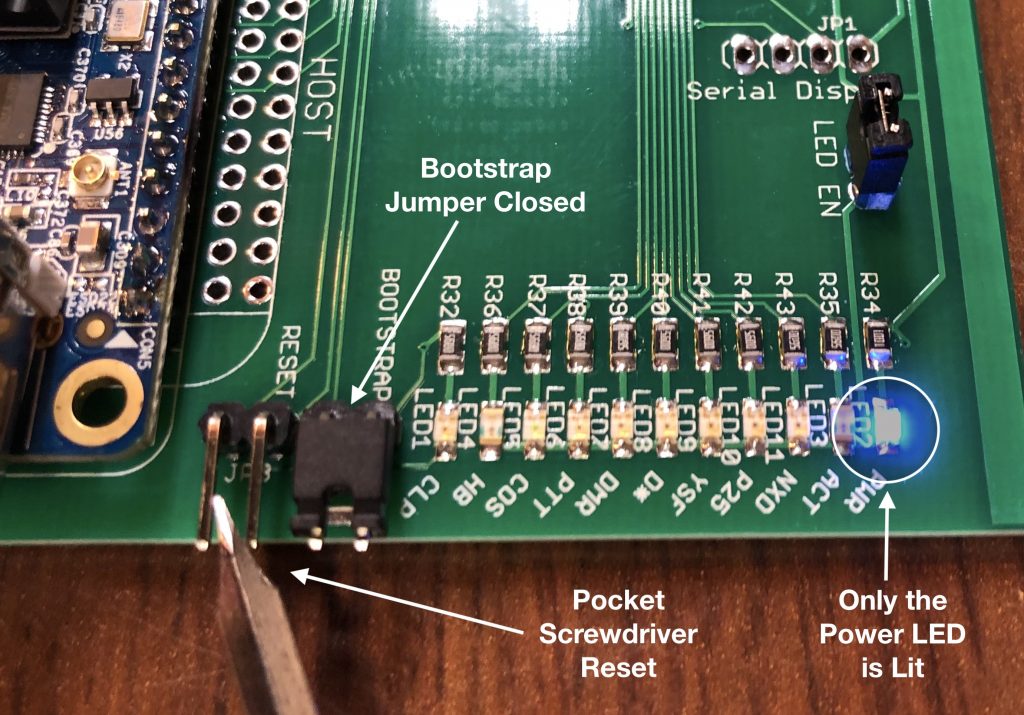
After “releasing” the reset, the PWR and orange ATC (activity) LED will be lit. Actually, the DMR and COR LEDs are also lit very dimly. I usually cannot even see them at all unless the room is dark. Scott’s board may be brighter. Once the flash write activity begins, the ACT LED will begin to blink. This continues until the end of the writing activity and the STM32 microcontroller resets.
The STM32 microcontroller will automatically reset after flash write is completed (that’s the -R in the command line string). Make sure the bootstrap jumper is removed before this, or when the board resets, it will come back up in bootloader mode again. If it does, no problem, just pull the jumper from the bootstrap header and short the pins on the reset header again. When the board resets (or powers up) in operating mode, you’ll see the light “dance” on the LEDs, then the HB (heartbeat) LED will start blinking. If the HB LED is not blinking, try resetting the board again, or just power-cycle the station.
That’s pretty much it for what I call the “manual” method of upgrade. Remember, MMDVMhost must not be running while upgrading firmware. There is only one Serial port between the HOST and MODEM; leaving MMDVMHost running means it will be trying to talk to the STM32 at the same time stm32flash is trying to load new code.
Automated Method: Make the Pi put the STM32 into bootloader mode
As I mentioned earlier the instructions from Repeater-Builder (v3, “blue board”) use the stm32flash command (on the unix host) to put the STM32 microcontroller into bootloader mode. I also mentioned that I’ve never gotten it to work properly – which is true. I suspect is has something to do with how the libraries are linked (or not) in the pre-compiled version and maybe expectations of the SBC being a RaspberryPi. Maybe it’s just me. I found another way to do this with both the OrangePI Zero and NanoPi NEO. My method involves using the WiringPi command line utility “gpio” directly, which I’ve also found to be handy in general when working with these boards.
I do not know if WiringPi is installed on the Pi-Star images for NanoPi NEO and OrangePi Zero. If not, they need to be. They are not installed by default with Armbian, so I had to install them initially. At this point, I’ve created my own images for both the Zero and the NEO and don’t have to think about these things anymore.
FriendlyArm makes the NanoPi NEO, with “official” information on installing WiringPi located here. Unfortunately the NEO/NEO2 version didn’t work, but I followed the instructions for the NanoPi M1 and it did – it just showed additional I/O pins not actually available on the NEO.
I used a 3rd party version for the OrangePi Zero that I found here. This version worked just fine out of the box.
Once installed, the first thing to do is run the command “gpio readall” to make sure things installed correctly. The output should look similar to this:
mmdvm@stm32-dvm-mtr2k:~$ gpio readall
 +-----+-----+----------+------+--Orange Pi Zero--+------+----------+-----+-----+
 | H2+ | wPi |   Name   | Mode | V | Physical | V | Mode | Name     | wPi | H2+ |
 +-----+-----+----------+------+---+----++----+---+------+----------+-----+-----+
 |     |     |     3.3v |      |   |  1 || 2  |   |      | 5v       |     |     |
 |  12 |   8 |    SDA.0 | ALT3 | 0 |  3 || 4  |   |      | 5V       |     |     |
 |  11 |   9 |    SCL.0 | ALT3 | 0 |  5 || 6  |   |      | 0v       |     |     |
 |   6 |   7 |   GPIO.7 |   IN | 0 |  7 || 8  | 0 | ALT5 | TxD3     | 15  | 198 |
 |     |     |       0v |      |   |  9 || 10 | 0 | ALT5 | RxD3     | 16  | 199 |
 |   1 |   0 |     RxD2 | ALT5 | 0 | 11 || 12 | 1 | IN   | GPIO.1   | 1   | 7   |
 |   0 |   2 |     TxD2 | ALT5 | 0 | 13 || 14 |   |      | 0v       |     |     |
 |   3 |   3 |     CTS2 | ALT3 | 0 | 15 || 16 | 0 | ALT3 | GPIO.4   | 4   | 19  |
 |     |     |     3.3v |      |   | 17 || 18 | 0 | ALT3 | GPIO.5   | 5   | 18  |
 |  15 |  12 |     MOSI | ALT3 | 0 | 19 || 20 |   |      | 0v       |     |     |
 |  16 |  13 |     MISO | ALT3 | 0 | 21 || 22 | 0 | ALT3 | RTS2     | 6   | 2   |
 |  14 |  14 |     SCLK | ALT4 | 0 | 23 || 24 | 0 | ALT4 | CE0      | 10  | 13  |
 |     |     |       0v |      |   | 25 || 26 | 0 | ALT3 | GPIO.11  | 11  | 10  |
 +-----+-----+----------+------+---+---LEDs---+---+------+----------+-----+-----+
 |  17 |  30 | STAT-LED |  OUT | 0 | 27 || 28 |   |      | PWR-LED  |     |     |
 +-----+-----+----------+------+---+-----+----+---+------+----------+-----+-----+
 | H2+ | wPi |   Name   | Mode | V | Physical | V | Mode | Name     | wPi | H2+ |
 +-----+-----+----------+------+--Orange Pi Zero--+---+------+---------+-----+--+
 mmdvm@stm32-dvm-mtr2k:~$
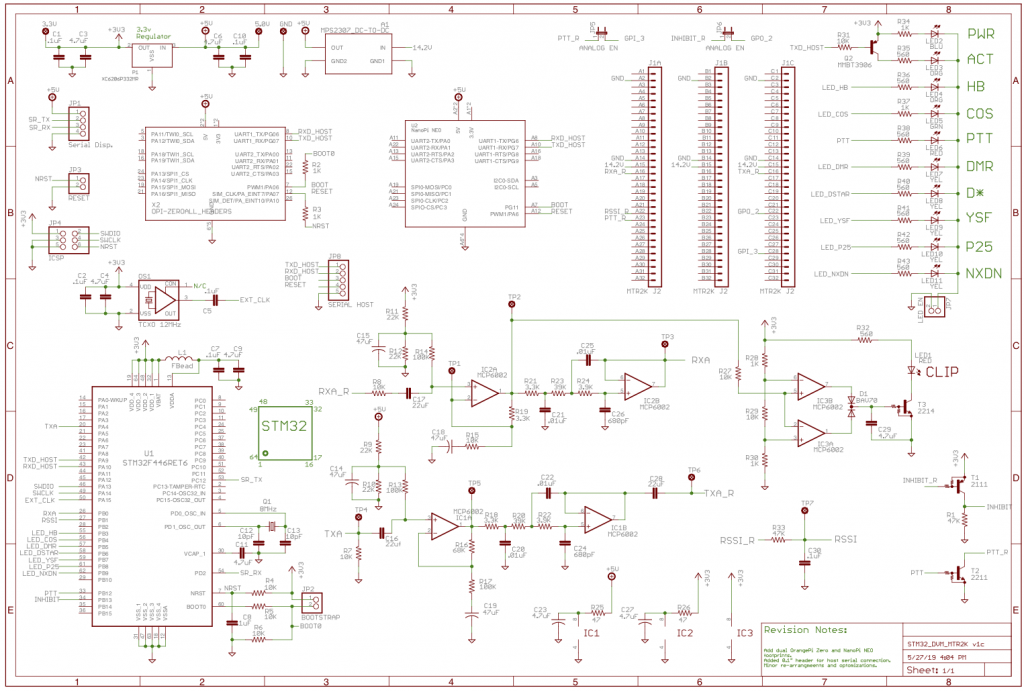
I arranged the PCB layout so that with either the OrangePi Zero or NanoPi NEO, the STM32 microcontroller bootloader enable pin is on GPIO 7 and reset is on GPIO 1. Everything I’m going to show from here on will work with either the Zero or the NEO.
All I have to do now is mimic what I did manually with jumpers on the right GPIO pins and I’m good to go! Note that by default these pins are set as inputs – that’s good, but it adds the steps of setting them to outputs first, and just for a bit of safety, I put them back to inputs at the end. Let’s take a look at the entire sequence of what I did at the linux command line to update a board. This sequence picks up after I’ve downloaded the firmware file to mmdvm’s (that’s the username on on the linux system, “mmdmv”) home directory, and that stm32flash and WiringPi are both installed:
mmdvm@stm32-dvm-mtr2k:~$ gpio mode 7 out
mmdvm@stm32-dvm-mtr2k:~$ gpio mode 1 out
mmdvm@stm32-dvm-mtr2k:~$ gpio write 7 1
mmdvm@stm32-dvm-mtr2k:~$ gpio write 1 0
mmdvm@stm32-dvm-mtr2k:~$ gpio write 1 1
mmdvm@stm32-dvm-mtr2k:~$ gpio write 7 0
mmdvm@stm32-dvm-mtr2k:~$ gpio mode 7 in
mmdvm@stm32-dvm-mtr2k:~$ gpio mode 1 in
mmdvm@stm32-dvm-mtr2k:~$ stm32flash -v -w ./mmdvm_f4.hex -R /dev/ttyS1
stm32flash 0.5

http://stm32flash.sourceforge.net/

Using Parser : Intel HEX
Interface serial_posix: 57600 8E1
Version      : 0x31
Option 1     : 0x00
Option 2     : 0x00
Device ID    : 0x0421 (STM32F446xx)
- RAM        : 128KiB  (12288b reserved by bootloader)
- Flash      : 512KiB (size first sector: 1x16384)
- Option RAM : 16b
- System RAM : 30KiB
Write to memory
Erasing memory
Wrote and verified address 0x0800fe50 (100.00%) Done.

mmdvm@stm32-dvm-mtr2k:~$
Ok, so that was probably just showing off a bit. Of course the real goal was to prove that worked, and then write a shell script to automate the process, but I thought you might like to see it all spelled out exactly as typed. The shell script below is “copy/paste” ready to go into your favorite text editor:
#!/bin/bash

echo "Setting Up GPIO Pins"
gpio mode 7 out
gpio mode 1 out

echo "Sending STM32 Device Into Bootloader Mode"
gpio write 7 1
gpio write 1 0
sleep 1
gpio write 1 1
gpio write 7 0

echo "Resetting GPIO Pins"
gpio mode 7 in
gpio mode 1 in

echo "Attempting to program STM32 device"
echo "The following output is from stm32flash:"
echo

stm32flash -v -w ./mmdvm_f4.hex -R /dev/ttyS1

echo "stm32flash completed"
Of course, no tutorial would be complete without showing a screen shot, right? Below is the output of my shell script running to update the MODEM code on a 1st production model STM32-DVM-MTR2K, using an OrangePi Zero:
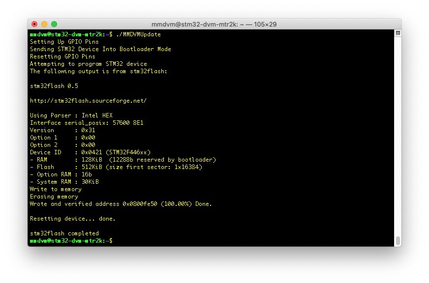
Wow. That was a really long article. There was a reason though – some of the background, things like installing WiringPi, will be referenced in future articles as we teach the STM32-DVM-MTR2K to do more neat tricks.
Oh yeah, and to get a higher raking on Google, here’s a cute cat picture for you. This guy lives with me and my family, and often keeps me company deep into the night down in the WA0EDA Skunkworks.

4 comments on “STM32-DVM-MTR2K: Deep Dive – Updating Firmware”
nv8q
May 28, 2019 at 6:21 pmWhat an absolutely beautiful cat.
Cort Buffington
May 28, 2019 at 6:44 pmAnd big… really big!
Steve E
January 2, 2020 at 8:59 pmRaspberry pi
Will your board support pi-star
I have a custom script that I have to run to connect to some MMDVM servers that are not public.
When in analog mode can one connect a Arcon controller to the accessory port on the repeater, to have echolink and IRLP options.
Cort Buffington
January 2, 2020 at 10:36 pmI’m not sure why you started the comment with “Raspberry pi”. There is not one on the STM32-DVM-MTR2K, there is a NanoPi NEO, which is a similar single-board computer, but uses a different SOC. There is a PiStar image for the NanoPi NEO. I know people have loaded it and reported no problems. I have never used PiStar, so cannot speak to differences in efficiency, heat, etc. I can tell you that I did not just drop a stock Armbian image onto the NEO, I have tuned it for this application. I have no idea how or if the NanoPI NEO PiStar version was tweaked.
I do not have an Arcom controller, so cannot guarantee there is a way to use it. I also am not entirely sure what you mean by “accessory” connector, as the MTR2000 has nothing with that name. I do believe that between the system connector, wireline connector (would require wireline board be installed) and the MRTI connector, this can be achieved.
What you cannot use is the Aux PTT and Aux TX Audio inputs on the system connector, as those are used internally by the STM32-DVM-MTR2K. The good news is that they’re not usually used anyway, since there’s no way to use the internal PL encoder with that TX input. I would look to the MRTI connector, or use the wireline board and a GPI with a wildcard table set to “key from wireline” as the PTT. Since the STM32-DVM-MTR2K replicates most of the useable functionality of the auxiliary I/O card, one of those is not needed.
I’m sorry I cannot answer more specifically – You’ve asked some very specific questions and I don’t like to give speculative answers as fact.